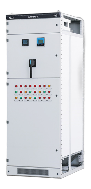
An APFC capacitor bank panel automatically switches capacitor steps to support the required power factor as the connected load changes. The panel is configured from the system voltage, measured or estimated load profile, existing power factor, target power factor, required compensation and harmonic conditions.
Zejiefu manufactures project-specific automatic power factor correction panels after the electrical data and installation requirements have been reviewed. The required kVAr, number of steps, switching method, reactor arrangement, protection and ventilation should not be selected from the service current alone.
APFC capacitor bank selection inputs
Use the APFC capacitor-bank sizing guide to estimate the initial kVAr from measured kW and power factor before the final engineering checks.
| Selection item | Information to provide | Design relevance |
|---|---|---|
| Electrical system | Rated voltage, frequency, phase arrangement and earthing system | Defines capacitor, switching and insulation requirements |
| Load profile | Maximum demand, typical operating demand and load variation | Supports total compensation and step distribution |
| Power factor | Existing value, target value and available utility records | Provides the basis for the required kVAr |
| Harmonic conditions | Measurements, nonlinear-load percentage, VFD and UPS information | Determines whether harmonic treatment needs engineering review |
| Switching duty | Load-change speed, switching frequency and response requirement | Influences contactor or thyristor-switched arrangements |
| Installation | Indoor or outdoor location, ambient temperature, IP rating and room ventilation | Defines enclosure, cooling and environmental provisions |
| Integration | Incoming supply, CT location, main board interface and communication requirement | Coordinates sensing, protection, cabling and controls |
Typical APFC panel configuration
- Automatic power-factor controller and current-transformer sensing circuit
- Project-defined capacitor stages and step sequence
- Capacitor-duty contactors or thyristor switching where specified
- Step protection, main isolation and internal control protection
- Detuned reactors where justified by the harmonic assessment
- Temperature management, ventilation and status indication
- Optional metering, alarms and communication points listed in the specification
Harmonics and detuned capacitor banks
Capacitor banks interact with the electrical network. Projects with variable-frequency drives, UPS systems, rectifiers or other nonlinear loads should provide harmonic measurements or the available power-quality study. A detuned reactor arrangement should be selected from the actual system data rather than assumed for every installation.
The quotation should identify the harmonic information used, the proposed reactor basis and any data still requiring confirmation. This avoids presenting an unverified standard configuration as suitable for every network.
Contactor-switched and thyristor-switched APFC
| Arrangement | Typical consideration | RFQ information |
|---|---|---|
| Capacitor-duty contactor switching | Common for loads that change at a moderate rate | Step size, switching frequency and operating sequence |
| Thyristor switching | Considered where rapid load changes require faster step response | Response requirement, load cycle and thermal conditions |
The final switching method must follow the actual load behaviour and approved project specification.
Where APFC capacitor bank panels are used
- Factories with varying motor and process loads
- Commercial-building main distribution systems
- Pumping, ventilation and utility installations
- Projects requiring centralized reactive-power compensation
- Energy systems where the load profile and harmonic conditions are documented
For related equipment, review the MCC motor control centre and main distribution board. Application context is available on the industrial facilities and solar and energy solution pages.
APFC capacitor bank RFQ checklist
- System voltage and frequency
- Existing and target power factor
- Maximum demand and operating load profile
- Required total compensation in kVAr, if already calculated
- Preferred step quantity or minimum step size
- Harmonic measurements, VFD/UPS loads or power-quality study
- Switching response requirement
- Installation environment, IP rating and room conditions
- CT ratio and proposed sensing location
- Quantity, destination country and requested documentation
Where the APFC panel forms part of a larger switchgear package, send the controlled SLD and BOQ for the switchgear RFQ. The IEC 61439 procurement checklist can help define assembly-level requirements.
Manufacturing and inspection basis
The approved electrical scheme, component schedule and general-arrangement drawing form the production basis. Review our manufacturing capability and quality and standards pages for the processes and documentation currently presented on this website.
APFC capacitor bank panel selection
An APFC bank is a capacitor bank panel with automatic step control. For a project quotation, the required panel cannot be selected from transformer capacity alone. The useful starting inputs are measured kW or kVA, existing and target power factor, system voltage, load variation and harmonic conditions.
| Selection input | Why it matters |
|---|---|
| Required compensation | Defines the initial capacitor-bank kVAr range |
| Load variation | Guides the number and size of automatic steps |
| Harmonic conditions | Determines whether reactor and capacitor-duty review is required |
| Installation environment | Influences enclosure, ventilation and ingress protection |
| Switching frequency | Influences contactor or other switching-device selection |
Use the APFC sizing guide for the initial calculation, then check the completed assembly scope against the IEC 61439 procurement checklist.
Frequently asked questions
What information is needed to size an APFC capacitor bank?
Provide system voltage, maximum and typical demand, existing and target power factor, load variation and harmonic information. These inputs are more useful than the service current alone.
Is one APFC capacitor bank size suitable for every project?
No. The required kVAr and step arrangement depend on the actual load profile, existing power factor and operating conditions.
When should detuned reactors be considered?
Projects with significant nonlinear loads or documented harmonic conditions should be reviewed using measurements or an available power-quality study. The reactor arrangement should follow that assessment.
Can the APFC panel communicate with a building or plant system?
Communication, alarms and remote status can be reviewed when the protocol, points list and interface requirements are included in the specification.
Can APFC equipment be integrated with the main LV board?
Yes, subject to the approved SLD, CT location, protection, cable or busbar interface, available space and thermal arrangement.
Request an APFC capacitor bank quotation
Send the electrical system data, load profile, power-factor information, harmonic data, quantity and destination. Zejiefu will identify missing selection inputs before preparing a project-based proposal.
Configuration inputs
Provide the single-line diagram, required standard, system ratings, installation conditions and preferred component make. Our technical response will identify the proposed scope and any deviations.
Available options
Electrical scheme, enclosure construction, cable entry, protection, metering, component make, IP rating, packing and documentation are configurable to the approved project scope.
Frequently asked questions
Can this equipment be manufactured to our SLD?
Yes. The final configuration is developed from approved drawings, ratings and component schedules.
Which documents are needed for a quotation?
Send the SLD, BOQ or specification, quantity, destination country and requested delivery schedule.
Are tests and reports available?
Available routine tests and documents depend on product scope. Only confirmed reports will be included in the proposal.