
A capacitor-bank enquiry often starts with a capacity: 100, 200 or 400 kVAr. Then comes a less obvious question: should the bank include reactors? A higher capacity does not answer it, and neither does the word “smart” on a capacitor module.
Use a detuned capacitor bank when the electrical assessment identifies a need to control capacitor–network resonance and harmonic loading. Where that assessment supports ordinary capacitor compensation, a bank without reactors remains an option. The decision depends on the network, connected equipment and operating conditions—not the cabinet size alone.
This guide explains the function of a reactor in a capacitor bank, what information supports the choice, and what to confirm in an APFC panel proposal.
For the wider selection process, read our APFC panel selection guide, covering load information, switching, phase control and proposal review.
1. Why is a reactor used in a capacitor bank?
A capacitor helps supply the fundamental-frequency reactive power required by inductive loads. However, the bank also interacts with the inductance of the supply network. At certain frequencies, that combination can amplify harmonics rather than leave them unchanged.
A detuned reactor is connected in series with the capacitor in the compensation branch. The reactor and capacitor are selected together to move the branch's resonant frequency away from the relevant harmonic frequencies. Its purpose includes limiting harmonic amplification and the associated stress on the capacitor. Schneider Electric explains this distinction in its introduction to detuned reactors.
The branch still provides power-factor correction. Adding a reactor does not turn it into a general-purpose filter that guarantees a specified harmonic level throughout the installation. If the project includes a harmonic-performance target, put that requirement in the specification and assess the filtering solution separately.
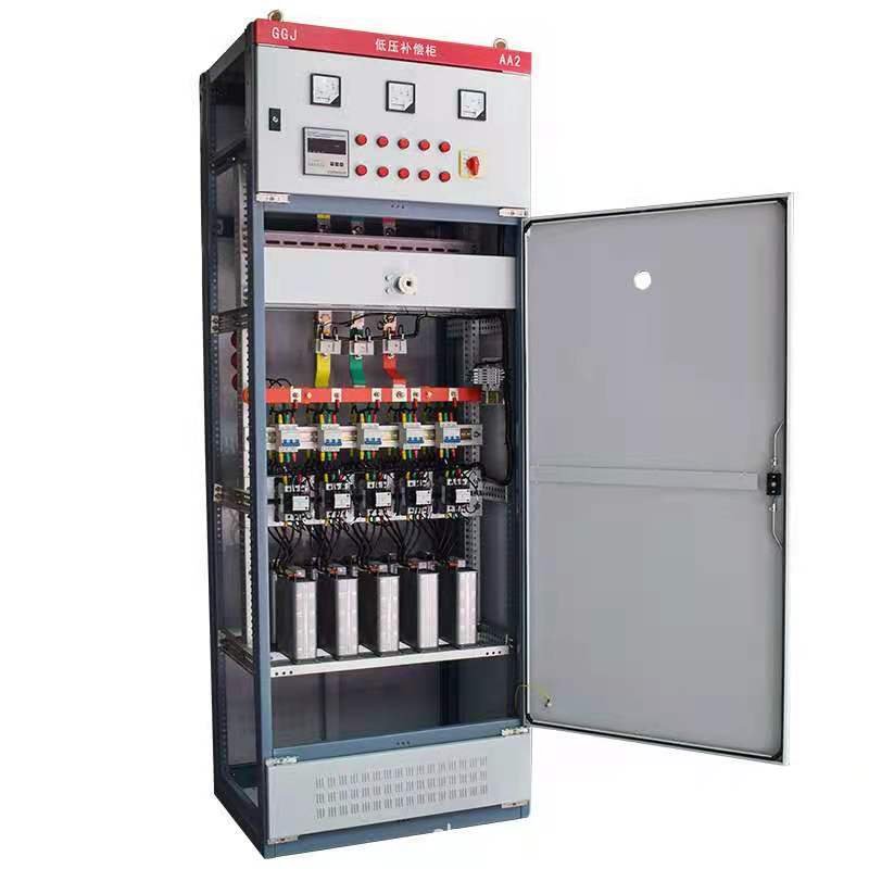
Conventional capacitor bank
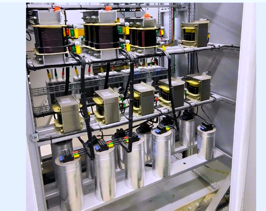
Separate reactors and capacitors
2. When should you evaluate a detuned APFC panel?
Review the harmonic conditions before choosing a plain capacitor bank when VFDs, UPS systems, rectifiers or other nonlinear loads form a material part of the installation. Also review them when an existing bank has unexplained problems or the supply arrangement is changing.
EV charging is another relevant application. In many of the charging projects we have worked on, the compensation cabinets use reactor-equipped capacitor arrangements. This is our project experience, rather than a rule that every charging installation needs the same equipment.
With AC charging, the AC-to-DC conversion normally takes place in the vehicle's onboard charger; with DC fast charging, conversion takes place in the offboard charging equipment. The converters can introduce harmonic currents into the AC supply. See Keysight's onboard-charger explanation and Yokogawa's EV charging power-measurement guidance.
For an EV charging site, establish two requirements separately: whether the installation needs additional fundamental reactive-power compensation, and whether its capacitor bank needs a detuned arrangement. Harmonic emissions alone do not establish the required capacitor kVAr. Ask for charger-model data and representative site measurements rather than assuming the full-load specification describes every operating condition.
Use the following situations to organize the discussion. They are reasons to investigate, rather than an automatic reactor-selection rule.
| What the project tells you | What to establish next |
|---|---|
| Several drives, UPS systems or rectifier loads share the bus | Their input technology, operating combinations and available harmonic records |
| Multiple EV chargers operate on the installation | AC/DC charger types, model-specific harmonic and power-factor data, simultaneous operation and measurements at representative charging loads |
| Capacitor fuses operate repeatedly, stages run unusually hot, or components fail | Inspection findings and measurements; investigate cooling, voltage and component condition as well as harmonics |
| Production is expanding or an existing capacitor bank is being enlarged | The network and harmonic conditions with the proposed stages in service |
| The installation can run from different transformers or a generator | The assessment for each intended supply mode, including compensation-control requirements |
| The specification requests a harmonic limit | The measurement point, operating conditions and performance to be verified |
A single total harmonic distortion reading does not describe the whole problem. Voltage distortion, current distortion and the individual harmonic spectrum answer different questions. The location and operating state of the measurement matter too. Eaton's power-factor-correction engineering guide discusses investigation and system analysis alongside capacitor selection.
For a new project without measurements, send the load schedule, transformer data and single-line diagram. Ask the designer or supplier to identify the assumptions and whether a harmonic study is needed. Missing data should remain an open engineering item, rather than becoming an unsupported claim that either arrangement is suitable.
3. How do 5%, 5.67%, 7% and 14% reactors differ?
A reactor percentage describes its reactance relative to the associated capacitor at the stated fundamental frequency. It is not a percentage of harmonics removed.
5% is a distinct detuning factor, not a shortened way of writing 5.67%. An Acrel technical article on low-voltage capacitor banks discusses 5% arrangements where the fifth and higher harmonics are the concern. Treat that as a configuration to assess against the actual network, not a fixed rule for an industry.
For an ideal series LC branch, the following relationship helps explain the differences. Here, p is the detuning factor expressed as a decimal, so 5% means p = 0.05:
Resonant frequency = system frequency ÷ √p
| Detuning factor | Approximate resonance at 50 Hz | Approximate resonance at 60 Hz |
|---|---|---|
| 5% | 224 Hz | 268 Hz |
| 5.67% | 210 Hz | 252 Hz |
| 7% | 189 Hz | 227 Hz |
| 14% | 134 Hz | 160 Hz |
Each table entry assumes a branch designed for the stated factor at the stated operating frequency. It does not describe one physical reactor/capacitor pair moved between networks. For unchanged ideal inductance and capacitance, the resonant frequency stays the same while the effective percentage changes. HYDRA explains this issue in its 50 Hz and 60 Hz capacitor-bank guidance.
At 50 Hz, the fifth harmonic is 250 Hz. The 5% branch's resonance is closer to it than that of a 7% branch. For equal capacitance and the same applied fifth-harmonic voltage, the ideal 5% branch has lower impedance at that harmonic and can carry more fifth-harmonic current. Closer tuning therefore calls for careful checking of component current duty, heating and tolerances; it is not automatically better filtering.
Where third-harmonic conditions are significant to the proposed circuit, 5% or 7% should not be assumed to provide the appropriate protection. A 14% arrangement places the ideal resonance below the third harmonic, but still requires review of the spectrum, circuit topology and component ratings. Schneider's harmonic-compensation guidance explains coordinated detuning choices.
For an EV charging site, the equipment category alone does not select 5% or 7%. Compare the measured harmonic conditions, network assessment and the manufacturer's matched configuration. Do not interchange a 5% and 7% reactor in an existing capacitor stage without recalculating the combination.
A proposal therefore needs more than “7%, 200 kVAr.” Confirm the operating voltage and frequency, the matched reactor/capacitor combination, stage arrangement and delivered bank output. Other detuning factors require the same project review; a larger percentage is not automatically a better choice.
The reactor also raises the fundamental-frequency voltage across its associated capacitor. The capacitor voltage rating must allow for that duty and the actual service conditions. Copying the supply voltage onto the capacitor specification is not enough.
4. Separate reactors or an integrated smart-capacitor module?
Once a reactor-equipped arrangement is justified, the next question is how to build it. Separate reactors and capacitors, and integrated reactor-equipped modules, are alternative assembly approaches. Compare the actual components and their installation requirements.
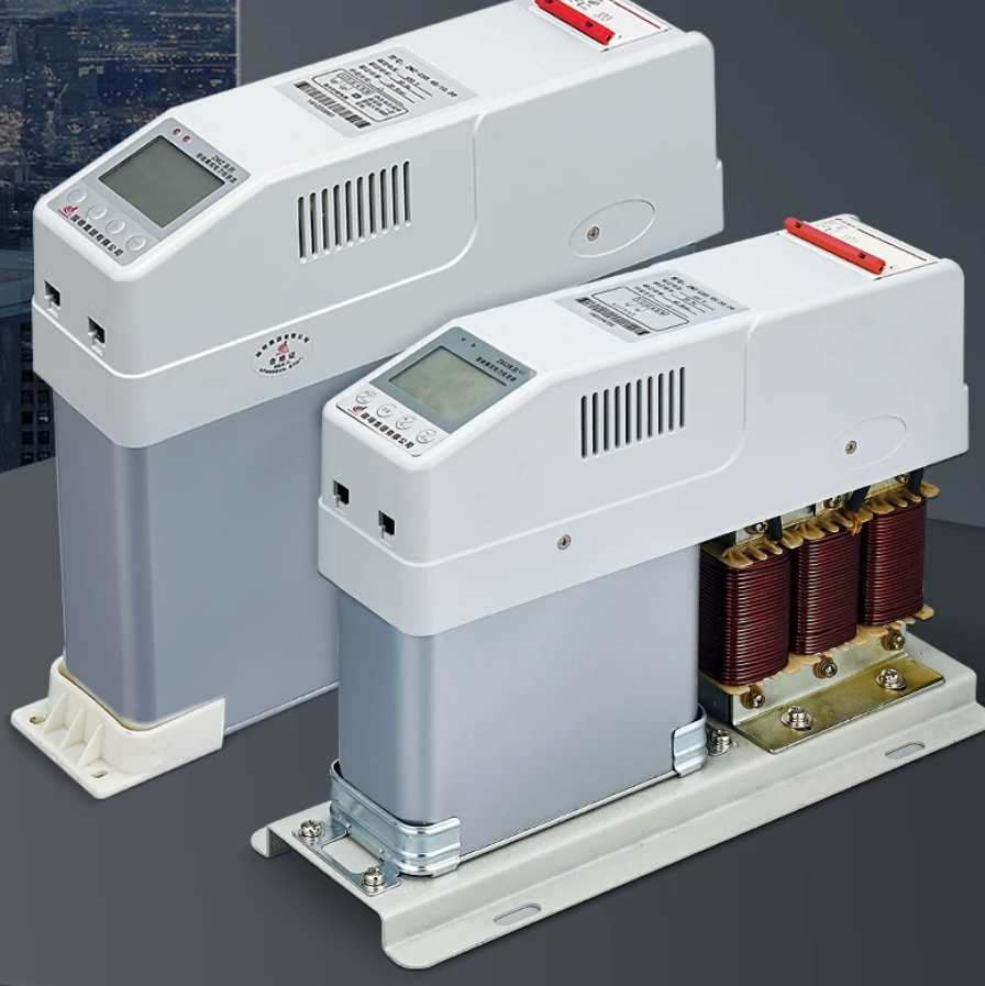
| Compare | Separate reactor and capacitor | Integrated reactor-equipped module |
|---|---|---|
| Component identification | Request the paired reactor and capacitor references | Request the exact module reference and its internal functions |
| Cabinet layout | Check component spacing, connections and access | Check module dimensions, installation orientation and connections |
| Thermal design | Account for component losses and airflow | Follow module heat-loss and ventilation requirements |
| Maintenance planning | Confirm what can be replaced individually and the approved matching parts | Confirm replaceable items, replacement procedure and spare-module availability |
| Control | Identify the controller, switching device and protection | Identify which functions are included and which remain external |
“Smart capacitor” does not by itself mean “with reactor.” For example, CHINT's BAGB/BAFB catalogue describes integrated measurement, control, switching and capacitor functions. The selected module's documentation must establish whether a reactor is included and what harmonic conditions it supports.
The photos here show equipment arrangements, not interchangeable ratings. A compact layout is useful only if the selected equipment also meets the electrical, thermal and service requirements.
5. What should an APFC panel with reactors proposal include?
Before approving the offer, ask for a coordinated configuration rather than a list of unrelated component ratings:
- Operating basis: voltage, frequency, supply modes and the harmonic information or study used.
- Bank output: delivered kVAr at the stated operating conditions, with individual stage sizes. Establish whether a quoted kVAr figure refers to a capacitor nameplate or the complete stage output.
- Matched equipment: reactor factor, capacitor ratings, component references and the manufacturer's pairing basis.
- Switching and protection: the proposed devices, duty and control interfaces. Reactor selection and stage-switching selection are related but separate checks.
- Heat and access: losses, ambient assumptions, cooling arrangement and maintenance clearances.
- Verification scope: the drawings, component information and inspection or test records included with the equipment.
Once the panel is in service, keep reactor and capacitor references with the stage readings. Our maintenance checklist for capacitor banks shows how to record the inspections and service findings.
This list is also useful when comparing two offers for the same total capacity. An unexplained difference should become a clarification before it becomes a purchase decision.
If the total capacity has not yet been established, use our APFC capacitor-bank sizing guide. The capacity calculation and the harmonic review answer different questions; both need to be resolved for the proposed arrangement.
6. What can you send if the project data is incomplete?
Start with the available information and identify what is missing:
System: voltage, frequency, transformer rating/impedance and available SLD.
Loads: major drives, UPS/rectifiers or EV chargers, existing compensation and expected operating combinations.
Measurements: available voltage/current harmonic records, their measurement point and operating state.
Requirement: target power factor or specified kVAr, installation conditions and delivery country.
Open items: unknown measurements, supply modes or specification requirements.
That gives the discussion a practical starting point without assuming the final reactor factor or component ratings. Scheme and drawing scope can be discussed against the project information. See our APFC capacitor bank panels for the equipment enquiry route.